Important Electronic Symbols Used In Electronic
Circuits
Like you have to understand how to read a road map to visit a
place, far away from your home town, the same goes for building electronic
circuits. The pictures below show typical examples of how to identify components
and important parts of a circuit. Components marked with a plus + sign must
always be connected correctly, as shown in the diagrams. In the case of
electrolytic capacitors, Wrong polarity will result in the capacitor exploding
and making a mess all around. It is important to remember that valves are far
more robust in the short terms, compared to transistors but also the Wrong
polarity of a rectifier diode will result in similar circumstances, possibly
causing more damage. I would advise you to read these pictures very carefully
before proceeding with any electronic circuit.
|
|
|
|
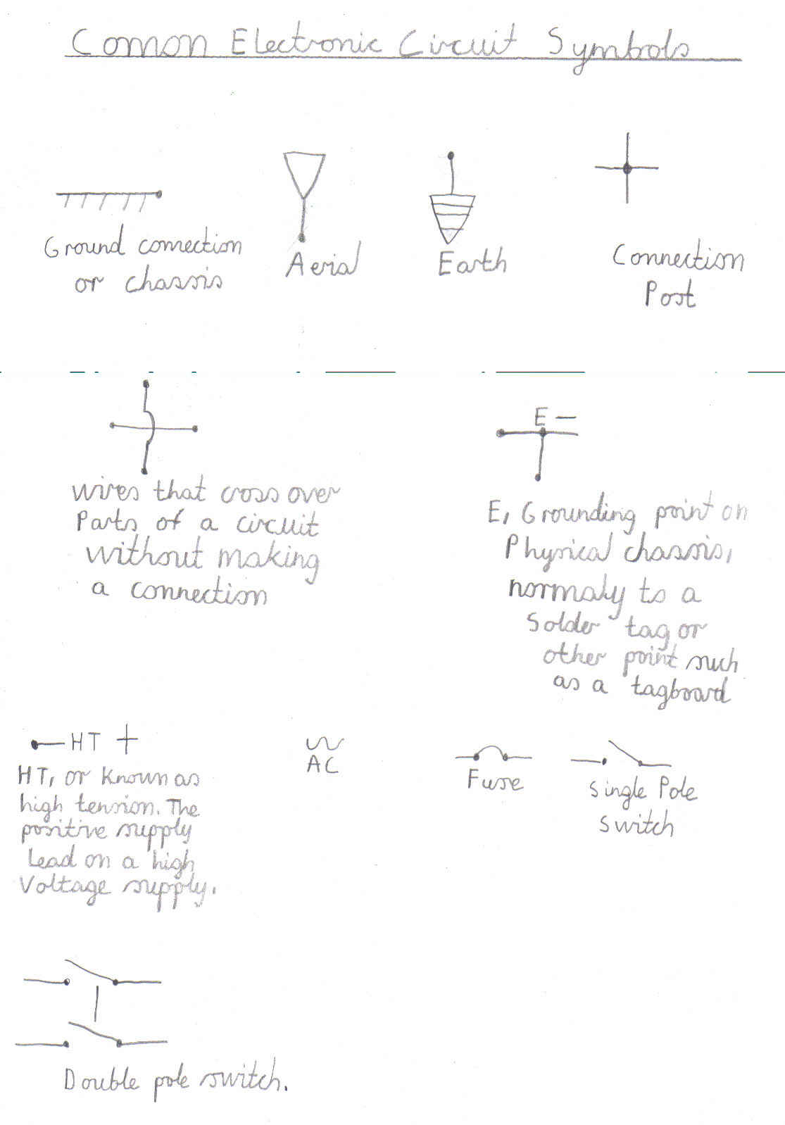
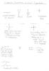
Important symbols and signs, regarding connections, on sections of electronic circuits
|
|

|
|
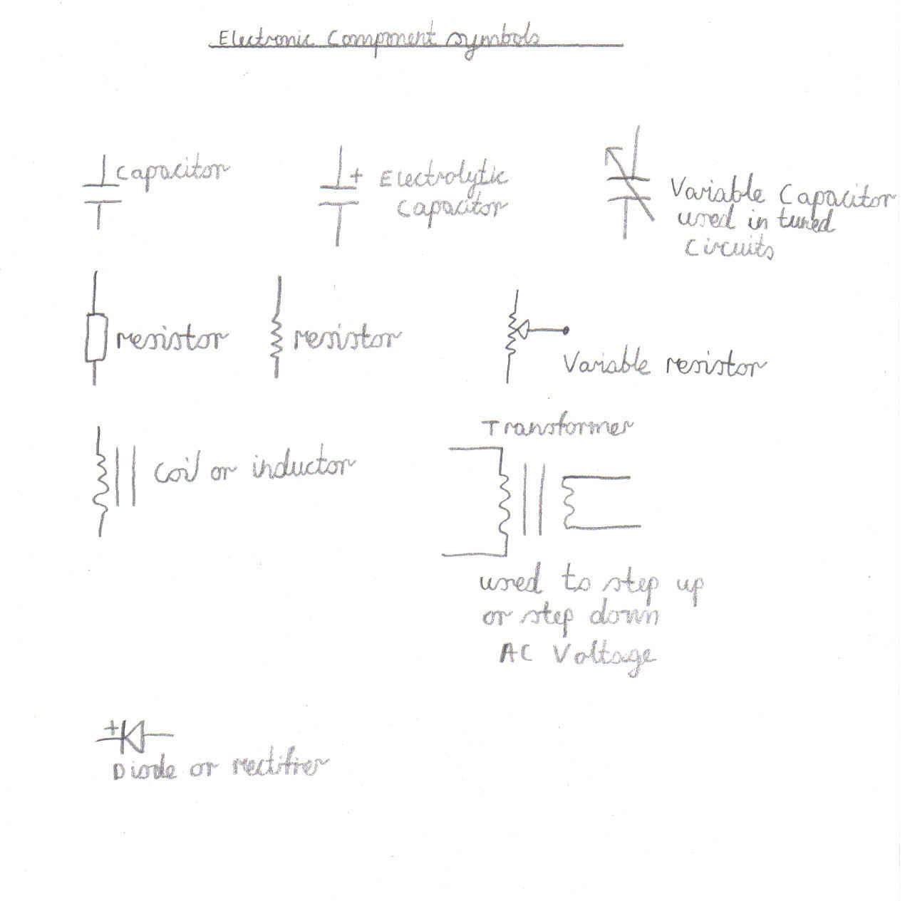
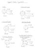
Typical component symbols, used in Electronic circuits and all my designs, on this website.
|
|
|
|
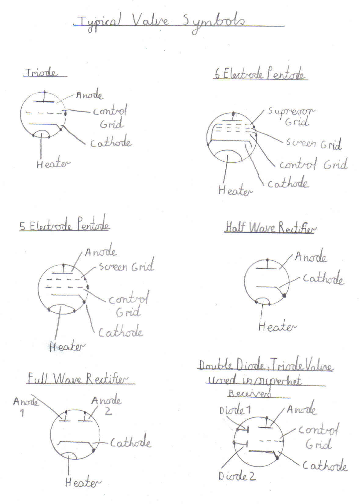
Same as component symbols, but relating more to the valves
|
|
|
|
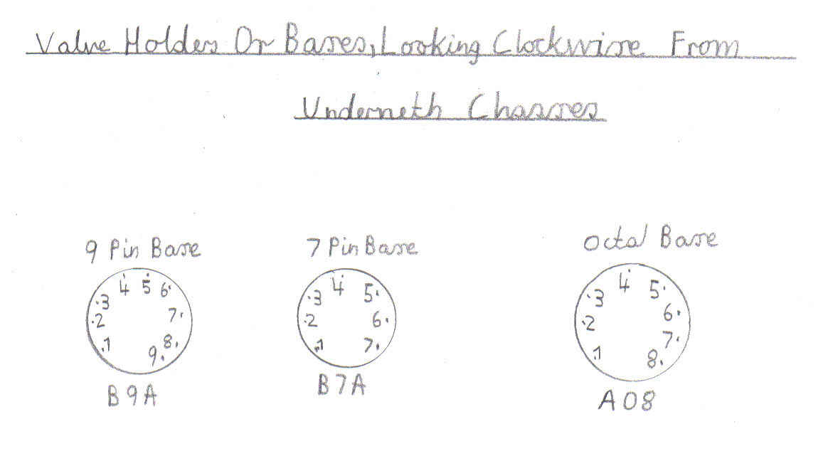
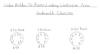
Important information, relating to Valve Base connections, when viewing underneth a particular radio chassis.
|
|
|
Please left click on selected image to enlarge
Home Page
Site Map Of All My Webpages And Favourite Valve Radio Related
Links